Blog
When Athletic Abilities Just Aren't Enough - Scoreboard Hacking Part 3
October 3, 2022
This is the final installment of a three part series on scoreboard hacking. Please go read parts 1 and 2 first if you have not been following along; they provide much of the background and context of this post. The sections are listed below:
- Introduction & Signal Analysis - Part 1
- Stealing the AES Key via Hardware Hacking - Part 2
- Full Protocol replication in Python and GNU Radio - Part 3 (This Post)
In the previous post, we found the AES key used for encrypting the packets via hardware hacking. To end the series, we will go through creating legitimate packets with Python and using GNU Radio to put the bits in the air. With the ability to create arbitrary packets, we will launch attacks against the scoreboard to impact real sporting events. Enjoy all of the shenanigans required to get this working :)
For a packet to be accepted, everything has to be perfect. Encryption, data whitening, CRC, baud rate... everything. Since we do not have a packet in an intermediate state, such as encrypted but not whitened, this complicates the matter further. We will have to perform both de-whitening and decryption consecutively to get our original data back. From a reverse engineering perspective, this is less than ideal but we must move forward! To start with this task, we will dive into the data whitening process.
Data Whitening
Data whitening is the process of randomly permuting bits being transmitted; the goal of the randomization is to guarantee no consecutive long string of only 0s or only 1s. In the case of the RF module, the benefit of the lack of consecutive strings is better clock synchronization between the transmitter and receiver. To replicate the effect of data whitening on the RF module, we will need to learn how the data whitening is performed. This is shown in Figure 1, which is from the RF module documentation.

Random data (more on this generation later) is XORed with the data to be transmitted ("transmit data" in Figure 1) that we want to send. The resulted is the whitened byte, which is the byte that is sent over the air. For example, 0x19 ^ 0xFF = 0xE6, where 0x19 is the transmit data, 0xFF is the random data and 0xE6 is the whitened(output) byte. The data whitening is why the length of the packets was wrong originally in part 1.
The documentation shows that a Linear Feedback Shift Register (LFSR) with a polynomial of X9 + X5 + 1 is used generate the random numbers for data whitening. "Woah woah woah," I hear you saying "What is an LFSR anyway?" Well, let's find out.
Continue Reading →
When Athletic Abilities Just Aren't Enough - Scoreboard Hacking Part 2
September 26, 2022
This is part two of a three part series. Please go through the first post in order to understand the background on the device. The sections are listed below:
- Introduction & Signal Analysis - Part 1
- Stealing the AES Key via Hardware Hacking - Part 2 (This Post)
- Full Protocol replication in Python and GNU Radio - Part 3
In the previous post, we discovered that the wireless traffic is encrypted using AES-128 ECB mode. In this post, we will go through how to uncover the AES key. Since this is done via hardware hacking, we must map out the hardware before we hack anything. It is hard(ware) to hack something without understanding how it works first!
PCB Mappings
Mapping out the entire PCB from a complete electrical level is not required. When I reverse engineer boards I think of three things: main components, communication lines and test points. All of this will be explained below.
Components on the Board

The chips on the boards have part information on them; nothing is scraped off or blank. For instance, one chip is labeled as Atmel ATMega328PB. Additionally, the silk screen is quite nice for documentation as well. This makes it substantially easier for us to reverse engineer what each component is doing. We can simply google the component identifier to find the documentation for the chip. Once we have the documentation for every component, we can understand what's the CPU, what's storage and everything else you need to know about the board to perform attacks.
The components on the scoreboard controller and receiver are listed below, with a picture of the receiver in Figure 1:
- ATMega328PB: An ARM MCU from Microchip. I commonly refer to this as the Atmel Processor and main processor below.
- RFM69HCW: RF module from HopeRF.
- Raspberry Pi 3 Model A+: A Raspberry Pi with HDMI, SD Card and other easy ways to interface.
- Splatch Antenna: A surface mount antenna.
Reading up on the part information provides a clean story for what is going on. The Atmel processor is the only large compute and storage on the board. Hence, it must decide what data to send wirelessly by sending it to the RF module. The RF module is magically converting the data and sending it wirelessly through the antenna. At this point, the RF module on the receiver interprets the data from the air and sends this to the Atmel processor on the receiver. Finally, the Raspberry Pi is receiving the data from the Atmel processor and displaying it over HDMI. With this, we now generally understand what every part does from reading about the documentation for the chips on the board. One of this understanding comes from recognizing the capabilities of the component and drawing logic conclusions from there. A generalization of this is shown below in Figure 2.
Communication Lines


For the RF module to send out data, something has to tell it what to do, right? So, figuring out the flow of data will get us closer to our goal of finding the AES key.
According to the RF module documentation, the only way to communicate with the chip is over SPI (more on how this works later). If this is the case, then the Atmel processor must be communicating with it over SPI.
The Atmel processor needs to talk to the Raspberry Pi as well. The Pi has a plethora of GPIO (General Purpose In/Out) pins that are connected between the two boards. Since this could be any protocol, this could be tricky to decipher. Sniffing the traffic & reverse engineering the firmware would allow us to figure this out; however, Jesse and I ended up seeing a class on the Raspberry Pi application (more on this later) with serial in the name. This made it fairly obvious that this communication line was serial but this could have been discovered in other ways.
Continue Reading →
When Athletic Abilities Just Aren't Enough - Scoreboard Hacking Part 1
September 19, 2022
Story
Growing up, I lived to play sports. Baseball, basketball, wiffleball.. Anything. And with all of those games, came lots of wins and losses. During many of these eventual losses, I looked up to the scoreboard and thought "What if I could change the score on the scoreboard?" If only I could control the scoreboard, then my team could win.
While watching a high school basketball game 10 years later, I had the question: could a somebody influence the outcome of a game by hacking the scoreboard? And now I had to know if this was possible. My 12 year old self's curiosity returned yet again. I had been nerd sniped. Over the next several months I acquired my HAM radio license hacked my parents garage door and learned all about wireless communication. This is where our story begins: the first hack of a wireless sports scoreboard.
The goal of these posts is to share the technical details and give you the ability to conduct similar research in the future. Knowing how this particular device works is awesome; but, it is more important to be able to draw these conclusions yourself. So, these posts are written from the perspective of the reader sitting in at each step in the process of hacking the device, hopefully drawing the same conclusions that I made along the way. To ensure I cover every interesting portion of the research, this will be a three part series:
- Introduction & Signal Analysis - Part 1 (This Post)
- Stealing the AES Key via Hardware Hacking - Part 2
- Full Protocol replication in Python and GNU Radio - Part 3
Overview of System


When purchasing the scoreboard, only two components are required: a controller and a wireless receiver. Both of these can be seen within Figure 1 and Figure 2 respectively. When purchasing this product, the company will also sell a shot clock receiver and an external horn. However, the main receiver can still perform all of this functionality so that is all my partner in crime Jesse Victors and I purchased. This is a cool idea, since this can scale to as many screens as the operator wants with the one-to-many relationship.
The controller, shown in Figure 2, is how the scoreboard operator would change the scoreboard. They can start or stop the game clock, add or subtract from the scores and control everything else on the scoreboard.
Continue Reading →
Finding an Authorization Bypass on my Own Website
March 3, 2022
My name is Maxwell "ꓘ" Dulin and I am a Senior Security Engineer who attempts to hack everything under the sun; from web applications to garage doors. Recently, an article about a SQL injection technique that exists solely in the main MySQL NodeJS library was released. This technique works by injecting a JSON object into a parameterized query that expects a string. While looking at the payload for this exploit, I wondered two things:
- Why does this attack work with a nested object?
- Is my website using NodeJs vulnerable to this attack?
Bypassing Escape Functions in mysqljs
The authors of the article did a wonderful job at explaining the attack and including a live demo. I will only be giving a quick summary of the initial part of the article; but, I encourage you to read the article and test out this bug yourself at the live demo from the post.
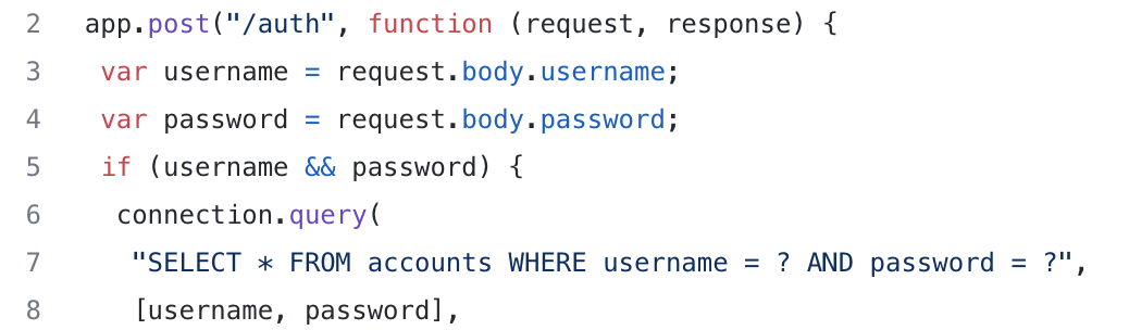
The article begins with a very simple NodeJs Express setup for a login endpoint; an image of this is shown in Figure 1. On lines 3 and 4, the username and password fields are put into local variables to be used in a query later. On lines 6-8, there is a classic SQL query that validates the user attempting to login matches the password on lines. This uses a parameterized query to add the request supplied username and password to prevent a SQL Injection.
The author then pulls out an exploit payload that looks nonsensical:
data = {
  "username": "admin",
  "password": {
    "password": 1
  }
};
The JSON object has two fields that are used: username and password. The object does not have a string for the password field though; instead, it has another object inside of the field. With the code snippet shown above and mysqljs as the library of choice for querying, the object shown above will completely bypass the authentication mechanism! To me, this seemed impossible since the code is using parameterized queries to prevent SQL injection. Therefore, I had to understand why this exploit works the way it does.
Why Does This Happen?
After going through the demo website for this, the reason for this bypass occurring still did not make sense to me. All I understood was that putting a very specific object bypassed the authentication flow. Why does putting a JSON object with very specific parameters bypass the authentication? In particular, what is the query parsing doing here? Since I was not satisfied with just knowing about the vulnerability, I decided to open up the source code to truly understand why this occurs.
Continue Reading →
Sears Garage Door Signal Reverse Engineering
January 4, 2022
Introduction
After seeing my hero Samy Kamkar's research into garage door remotes called Open Sesame, I got interested in software defined radios (SDRs). In particular, I was curious what other items would be vulnerable to replay, interception and other types of attacks. Leading up to some other research (stay tuned!), I dove into my childhood home's electronic garage door opener. This garage door remote is labeled as the Sears Craftsman 139.53708 Garage Door Remote, which was originally manufactured 30+ years ago. Even though this device is old, this post is more about reversing radio signals and recreating the signal ourselves.
In this article, we will dive into the reverse engineering of wireless signals with off the shelf tools and how to launch practical attacks against these wireless systems.
How Does This System Work?
Remote
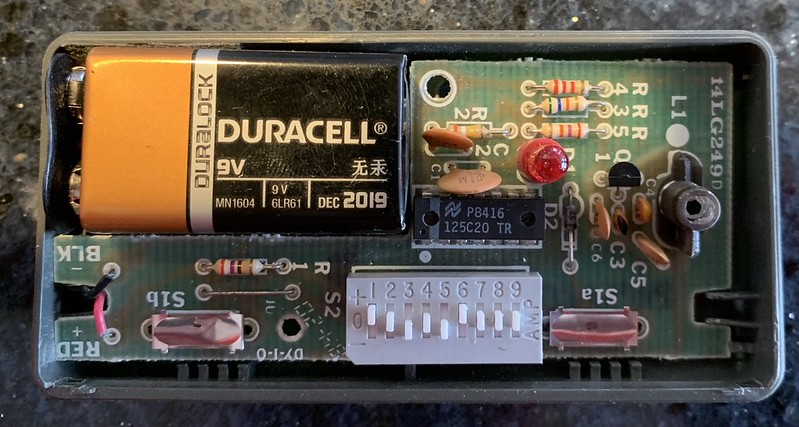
The remote has 9 DIP switches. These are used to configure the secret code that is transmitted to unlock the garage door. Each of these switches has three options: +, 0 and -. Most data transmission is binary in nature. This was interesting since we had a ternary code as opposed to the traditional binary code. All of this information can be seen in Figure 1 above.
The main schematic for this alluded me for a long time, where I initially thought that the main chip was ADC from the P8416. However, with inquiries from Gene Berkowitz and Scott LaBombard after I initially posting this article, I learned the true nature of the device! P8416 indicates the production code: China (P) and the 16th week of 1984. Then, the actual chip part is 125C20. The naming conventions on chips are new to me but I was linked a good resource at chipdocs, which helps quite a bit.
The 125CXXX chip is really a ternary encoder that takes input from the DIP switches. Since the product is a proprietary and owned by Chamberlain, then sold by Sears, there are no public datasheets for this exact product. However, since this is a family of products, there is a schematic for a generic Chamberlain garage door remote that should be fairly similar to our remote. The FCC ID on our target remote returns no information, sadly. Sometimes, venturing off into similar products can be useful for reverse engineering your target if there is no documentation on your target. Good to know!
Syncing
The receiver (door opener) has a button on the side of it. This button is used to sync the receiver with the remote. To reprogram the receiver, this button needs to be pressed then we send our new code from the remote. At this point, the code has been changed on the garage door receiver. This is interesting to me since I expected for a similar DIP switch to be on the receiver as the transmitter but this was not the case.
Signal Analysis
When analyzing signals, there are many components of a signal to consider. Three of the most important are mentioned below:
- Frequency
- Modulation
- Encoding scheme for bits
Continue Reading →